Learning about the Lathe - part 5 - Everyday - Turn, turn, turn
No apologies to The Byrds! At last we have a small pile of swarf to show for all this effort and the beginnings of what might be a wheel for my locomotive - it may just turn out to be a piece of scrap to use as ballast but at least we're trying now.
I've been through one of those strange periods of inertia, having ordered some tools from a company who came very well recommended and waited and waited, they say they were waiting for part of my order to come in, then it was Christmas and New Year, there was no spare cash and no tools either. So when pay day came around I abandoned all hope of ever seeing that order and rang Peatol for a set of 6 cutting tools which arrived within days and are now being used.
There's no point in my writing it all down about the tools - just go to Carter Tools' great site for a full description and basic userguide.
A few points of interest to pass on - lathes should turn anti-clockwise as you look at the headstock from the tailstock. Otherwise the chuck unscrews as soon as you try and do any work. Sounds obvious but you have to check - I'll say no more except that no damage was done to the lathe, the chuck, or me in learning this lesson! This is the kind of basic information that doesn't seem to be written down anywhere obvious - which is one of the reasons I'm writing this.
Turning makes a mess! swarf piles up everywhere. A nice soft 3" paintbrush is useful for weeping it all up - and do this you must because ferrous swarf rusts and you don't want a rusty lathe. (No - I am not, for once, speaking from experience!)
Turning (!) to the job in hand....
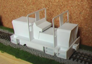
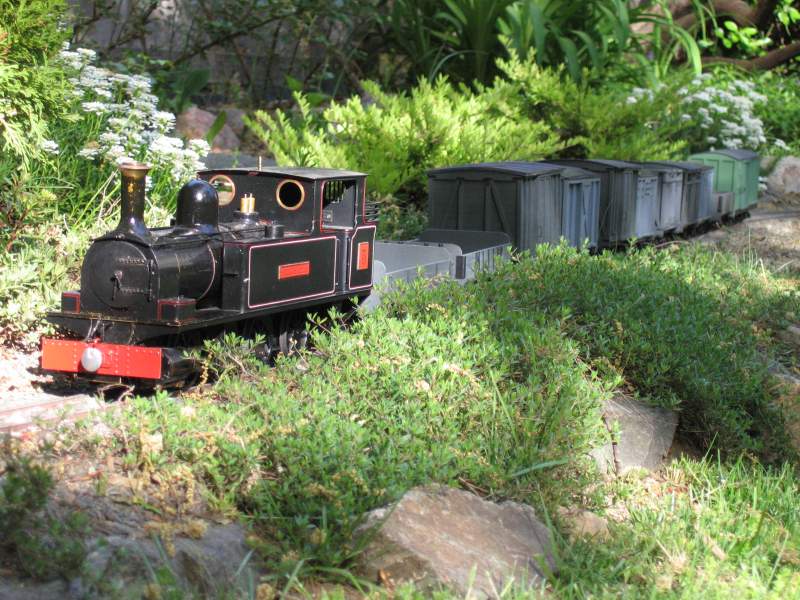
I probably didn't choose the easiest piece of work to start with, but I thought I should start at the beginning of the instructions and work my way through, so job one on the lathe was to turn a pair of driving wheels for the deWinton. This job calls for a 17mm length of steel bar, 27mm in diameter. So first you have to saw a length from off of your stock - a real job in itself, as the steel is quite hard. A point to note here is that this is likely another indicator of where "having the right tools" proves again to be right. Just what is the right tool though? I guess a nice new, sharp hack saw blade would have been best, I improvised this time, but will try and do it right for the next time. I'm saying this now because I am all too aware how expensive it can be to have to buy all these "right tools " from scratch, but sometimes the best to hand has to do, even though it may take longer and be less neat......
Anyway, I now have a hunk of steel, and I need to mount it in the lathe chuck. Mine is a 4 jaw chuck which means that I have to get into truing up with a dial indicator. Another of those "right tools", and in this case you also need a suitable mount or stand - I was lucky in that mine can be just about mounted in the toolpost, but I shall have to make a proper mount soon enough. Once again, Nick Carter has a good "how to" article on his Carter Tools website. Nick's is permanently mounted on top of the headstock via a series of arms and elbows and is arranged so as to have the gauge directly above the work. If you have a 3 jaw chuck, then you don't have to do any of this and can move straight on to the turning bit:
Facing the ends is a matter of picking the right tool..... the round nose tool is good for this, the idea being to end up with a nice smooth, polished end - I find feeding the tool slowly across the work with a very light cut (ie not taking off much metal at all) works best, once you have got things squared up.
Use the right handed cutter to work up the tread, basically you remove 3mm of metal 4.5mm along the work, I put a mark on the work with my digital calipers at 4.5mm, then placed the cutting edge of the tool on the mark, then locked the carriage stop to prevent the tool going any further. Turning is then a matter of taking the metal off a bit at a time - the lathe talks to you as you cut and will soon let you know if you push it too hard.
Now it is starting to look like a wheel, and so we move onto the recess. Hmmm - I wondered, I guessed and I tried, and in the end asked how it should be done - and as usual got several answers. One problem is how to know just where to cut, the best answer being to black up the end (use a permanent marker pen) and set a pair of dividers or similar to the inner and outer diameters and scribe 2 circular marks. This is me thinking ahead after the event, and I suspect a small indent made with a centre drill may assist with this operation.
Postscript
At the end of all this I separated the 2 wheels with a (nice new) hacksaw and faced the backs - only to realise that I hadn't tapered off the flanges - this is probably a job that can't be done retrospectively because there isn't enough metal to get a grip on AND do the job - so it may be that these 2 get put down as a practice run. I have however managed to face and parallel bore 2 brass cylinders though. More soon!
I've been through one of those strange periods of inertia, having ordered some tools from a company who came very well recommended and waited and waited, they say they were waiting for part of my order to come in, then it was Christmas and New Year, there was no spare cash and no tools either. So when pay day came around I abandoned all hope of ever seeing that order and rang Peatol for a set of 6 cutting tools which arrived within days and are now being used.
There's no point in my writing it all down about the tools - just go to Carter Tools' great site for a full description and basic userguide.
A few points of interest to pass on - lathes should turn anti-clockwise as you look at the headstock from the tailstock. Otherwise the chuck unscrews as soon as you try and do any work. Sounds obvious but you have to check - I'll say no more except that no damage was done to the lathe, the chuck, or me in learning this lesson! This is the kind of basic information that doesn't seem to be written down anywhere obvious - which is one of the reasons I'm writing this.
Turning makes a mess! swarf piles up everywhere. A nice soft 3" paintbrush is useful for weeping it all up - and do this you must because ferrous swarf rusts and you don't want a rusty lathe. (No - I am not, for once, speaking from experience!)
Turning (!) to the job in hand....
I probably didn't choose the easiest piece of work to start with, but I thought I should start at the beginning of the instructions and work my way through, so job one on the lathe was to turn a pair of driving wheels for the deWinton. This job calls for a 17mm length of steel bar, 27mm in diameter. So first you have to saw a length from off of your stock - a real job in itself, as the steel is quite hard. A point to note here is that this is likely another indicator of where "having the right tools" proves again to be right. Just what is the right tool though? I guess a nice new, sharp hack saw blade would have been best, I improvised this time, but will try and do it right for the next time. I'm saying this now because I am all too aware how expensive it can be to have to buy all these "right tools " from scratch, but sometimes the best to hand has to do, even though it may take longer and be less neat......
Anyway, I now have a hunk of steel, and I need to mount it in the lathe chuck. Mine is a 4 jaw chuck which means that I have to get into truing up with a dial indicator. Another of those "right tools", and in this case you also need a suitable mount or stand - I was lucky in that mine can be just about mounted in the toolpost, but I shall have to make a proper mount soon enough. Once again, Nick Carter has a good "how to" article on his Carter Tools website. Nick's is permanently mounted on top of the headstock via a series of arms and elbows and is arranged so as to have the gauge directly above the work. If you have a 3 jaw chuck, then you don't have to do any of this and can move straight on to the turning bit:
Facing the ends is a matter of picking the right tool..... the round nose tool is good for this, the idea being to end up with a nice smooth, polished end - I find feeding the tool slowly across the work with a very light cut (ie not taking off much metal at all) works best, once you have got things squared up.
Use the right handed cutter to work up the tread, basically you remove 3mm of metal 4.5mm along the work, I put a mark on the work with my digital calipers at 4.5mm, then placed the cutting edge of the tool on the mark, then locked the carriage stop to prevent the tool going any further. Turning is then a matter of taking the metal off a bit at a time - the lathe talks to you as you cut and will soon let you know if you push it too hard.
Now it is starting to look like a wheel, and so we move onto the recess. Hmmm - I wondered, I guessed and I tried, and in the end asked how it should be done - and as usual got several answers. One problem is how to know just where to cut, the best answer being to black up the end (use a permanent marker pen) and set a pair of dividers or similar to the inner and outer diameters and scribe 2 circular marks. This is me thinking ahead after the event, and I suspect a small indent made with a centre drill may assist with this operation.
Postscript
At the end of all this I separated the 2 wheels with a (nice new) hacksaw and faced the backs - only to realise that I hadn't tapered off the flanges - this is probably a job that can't be done retrospectively because there isn't enough metal to get a grip on AND do the job - so it may be that these 2 get put down as a practice run. I have however managed to face and parallel bore 2 brass cylinders though. More soon!
posted by John Sharp at 11:42 PM
1 comments
![]()
![]()